Reverse osmosis systems are far more than a simple combination of membrane housings and pumps; they represent separation engineering grounded in thermodynamics and materials science. Understanding their underlying principles is the cornerstone for achieving efficient, stable operation and maintenance.
01 Reverse Osmosis Technology
When discussing RO, most people only know it as “forcing water through with pressure.” While vivid, this description is overly simplistic and even misleading. True RO is a meticulously orchestrated “reverse assault” against natural laws.
1. Osmosis: Nature's Law Imagine separating pure water and saltwater using a membrane that only allows water molecules to pass. In its natural state, water molecules spontaneously migrate from the pure water side through the membrane into the saltwater side, attempting to dilute the saltwater to achieve concentration equilibrium. This process is osmosis. The driving force behind this natural process is osmotic pressure.
2. Reverse Osmosis: Industry's Counterattack To obtain pure water from the saltwater side, we must counter this natural process. We apply an external pressure exceeding the osmotic pressure on the saltwater side, forcibly “squeezing” water molecules back through the membrane to the pure water side. Impurities like salts, colloids, and organic matter are retained by the membrane. This “defying nature” process is reverse osmosis.
Key Formula: Calculating Osmotic Pressure Osmotic pressure is not a fixed value; it can be estimated using the van't Hoff equation: π = i × C × R × T
π: Osmotic pressure
i: Van't Hoff factor of the solution (for NaCl, i≈2)
C: Molar concentration of the solution
R: Ideal gas constant
T: Absolute temperature
Professional Insights:
Temperature Impact: The T in the formula indicates that higher water temperatures increase the feedwater osmotic pressure, requiring higher operating pressure. This explains why RO operating pressures need differentiated adjustments between winter and summer.
Dynamic Concentration Changes: During RO operation, the concentration C increases continuously from the feedwater side to the concentrate side of the membrane element. This means osmotic pressure varies across different positions within the membrane element, with the highest scaling risk occurring at the concentrate end.
3. Separation Mechanism: How does the membrane achieve “selective” permeation? While the “sieving theory” is widely circulated, it is not entirely accurate for explaining RO. For mainstream polyamide composite membranes, the theory is: Dissolution-Diffusion Model:
Water molecules first dissolve into the polymer network of the membrane material. They then diffuse through the membrane layer under pressure-driven concentration gradients. Finally, they desorb onto the product water side. Ions and molecules with larger hydration radii are retained because their “dissolution” and ‘diffusion’ capabilities are significantly weaker than those of water molecules. This process resembles a “molecular-level race” rather than simple “sifting.”
02 Reverse Osmosis Membrane Elements
Membrane elements form the heart of RO systems, with their technological sophistication determining the system's performance ceiling.
1. Materials Science Revolution: Polyamide Composite Membranes
Today's mainstream RO membranes are no longer homogeneous cellulose acetate membranes. Instead, they are polyamide thin-film composite membranes produced via interfacial polymerization. They consist of three layers:
Polyester nonwoven support layer: Provides mechanical strength.
Polysulfone porous interlayer: Provides structural support with a smooth surface.
Polyamide desalination layer: An ultra-thin, dense layer approximately 200 nanometers thick, serving as the core for salt rejection.
The advantages of this structure include: extremely thin desalination layer (high flux), excellent chemical stability (wide pH tolerance range), and high salt rejection rate (>99%). However, its Achilles' heel is extreme sensitivity to oxidants (e.g., residual chlorine), which can cause irreversible degradation.
2. The Intrinsic Relationship of Key Performance Parameters
Understanding parameters is key to understanding the membrane. Salt rejection rate: The membrane's ability to retain salts. Salt rejection rate = (1 - Product water salt content / Feed water salt content) × 100%. This directly reflects the membrane manufacturer's technical proficiency. Water Flux: The volume of permeate produced per unit area of membrane per unit time. Excessively high flux accelerates fouling; excessively low flux increases capital investment. A balance must be sought in design and operation. Recovery Rate: Recovery Rate = Permeate Flow Rate / Feed Flow Rate × 100%. Increasing recovery rate conserves water but elevates concentrate side concentration, heightening scaling and fouling risks. Deep Interdependence: These three parameters constrain each other. At constant pressure, increasing recovery rate raises average feed concentration and osmotic pressure, thereby reducing net driving pressure and lowering product water flux. Simultaneously, higher concentrate concentration increases the driving force for salt permeation through the membrane, potentially causing a slight decrease in salt rejection rate.
03 System Engineering Logic
An excellent RO system incorporates preventive logic into its very design.
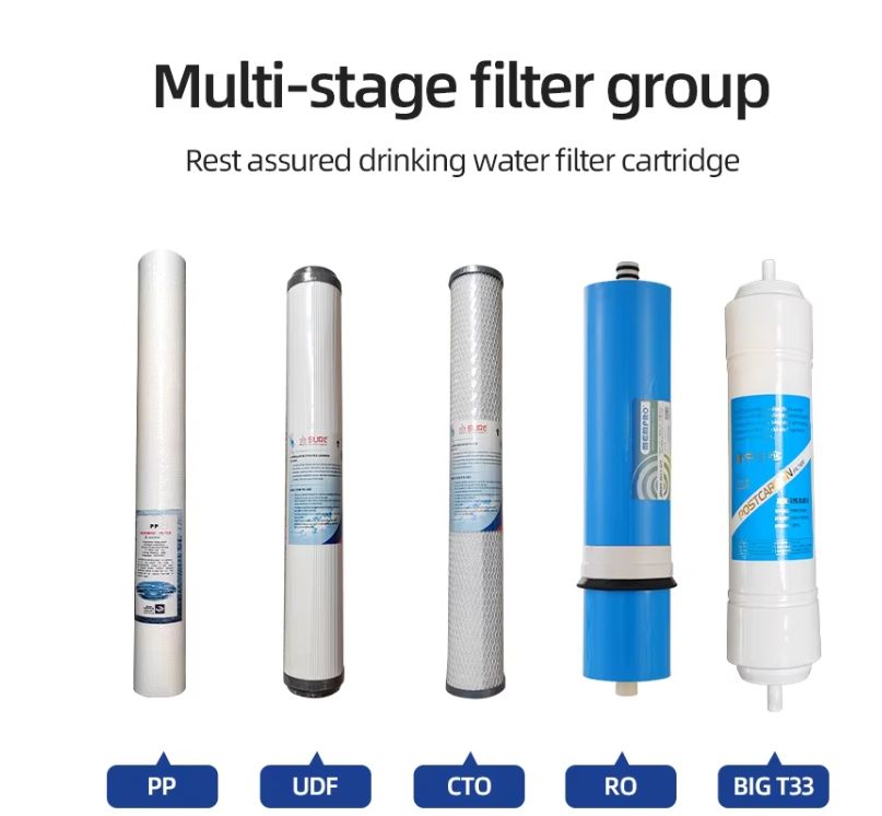
1. Pretreatment:
The “Immune System” of RO Pretreatment has one sole objective: to meet the feedwater requirements of RO membranes. Its design is entirely determined by the raw water quality and the sensitivity of the RO membranes. Multimedia filtration removes suspended solids, activated carbon adsorbs residual chlorine, softening removes hardness, chemical dosing inhibits scaling... Each step serves as a protective barrier for the “heart” of the system.
2. The Art of Membrane Housing Arrangement and Stages/Passes
Why not simply connect membrane housings in parallel? The goal is to maximize feedwater utilization and enhance system recovery rate within limited pressure constraints.
Stage: Membrane elements connected in parallel handle primary product water production.
Stage: Receives concentrate from Stage 1 for secondary separation, recovering additional product water.
Pass: Refers to product water being pressurized and re-processed through the RO system to further enhance water quality, commonly used in ultrapure water production. The classic “2:1” configuration (6 membrane housings in Stage 1, 3 in Stage 2) balances flux distribution across stages, preventing contamination and blockage in Stage 2 due to insufficient flow.
3. The System's “Neural Network”
Each critical instrument serves as a diagnostic window: Feed/concentrate pressures calculate inter-stage pressure differentials to assess contamination. Product water flow is a core performance metric, with its normalized value being a key indicator of fouling. Feed/product water conductivity directly reflects changes in salt rejection rate. The SDI meter provides online monitoring of pretreatment effectiveness, serving as the RO system's “sentinel.” Only by understanding the intricate dynamic equilibrium between pressure, concentration, and flux can one remain confident and resourceful when confronting the myriad challenges encountered in the field. In subsequent articles, we will delve deeper into practical aspects such as pretreatment, chemical cleaning, and fault diagnosis.
 Analysis of the Structure and Working Principle of Ultrapure Water Equipment
 Tips for Using Home Water Purifier Filter Cartridges
 The Battle of Four Membranes: Microfiltration, Ultrafiltration, Nanofiltration, Reverse Osmosis—Which Reigns Supreme in Water Purification?
 Don't Pay for Stupidity! The Ultimate 2026 Water Purifier Guide: Selection, Pitfalls, and Maintenance All in One Article